Hierarki Blocks in gSchem
So, hierarki block in gschem, is not that easy as in other EDA tools. First you have to create the subcircuit, and then you have to create the symbol, that you then can put in your overview circuit.
This is a feature that is quite useful, as then you can create a modular circuit, this mean that if you have a circuit that you will reuse, or if you just want a better overview over of your diagram.
For example, take a look at the gTAG circuit from the geda-example package on my machine it is located, at /usr/share/doc/geda-examples/examples/gTAG :
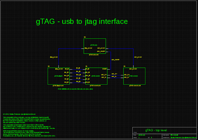
Of course I use this example, because this a uses hierarki block schematic, but as you can see this is useful when you have a big schematic, to put you circuit into smaller section. Or if you just want to reuse an “old” schematic. The blocks attributes is shown on the following picture:
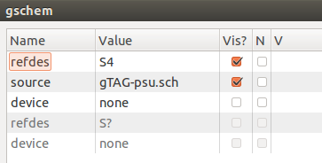
As we can see it has an attribute called “source” which directs it to “gTAG-psu.sch”, this directs the gschem to the circuit represented by the symbol called, “gTAG-psu”. So if we want our schematic to have this hierarki blocks, then we need to create a symbol and a schematic before we can add it the overview schematic. Hopeful some day, an feature to gschem is added, so you just can draw an square, slap some pins on it and it will create the symbol and underlying schematic, with the inputs and output in it.
But until further, I have created a script that, takes an schematic and creates a block symbol from it. There is some limits on this scripts, so I will name them here:
- Use of symbol: “in-1.sym” to indicate a input port
- Use of symbol: “out-1.sym” to indicate a output port This scripts, will create a file called “yournameofsch.src”, this file is a tragesym file, that then is need to be put through “tragesym” to create the symbol for your circuit. Add this symbol to your schematic, open the attributes for this symbol, and add “source=yournameofsch.src” to it. This is so that it points to your circuit. Then you should be done, do this for all your subcircuits.
Just a warning, this script is not mean to be a permanent solution, this is only a temporary solution for this. I am also currently working on a new version, that does not rely on “tragesym” to create the symbol, but could take awhile before this is done.
The script can be found on github.com
Hopes this help somebody.
Flindtathome has found a better solution
He has found there is some problem with the script, in the way I have designated the subcircuits. I think the solution he has found is a far better option, please use it instead of the script.
Flintathome the 30. april 2016
Hey. Interesting little script :)
I am having some difficulties creating netlists when using sub circuits in gschem. I have a simple voltage divider with two resistors (R1 and R2, just to keep things simple for testing), and use it 3 times in a schematic. Netlisting with gnetlist does not complain and I get
*============== Begin SPICE netlist of main design ============
V1 1 0 DC 1V
S1/R1 1 out1 1k
S1/R2 2 out1 1k
S2/R1 2 out2 1k
S2/R2 6 out2 1k
S3/R1 6 out3 1k
S3/R2 0 out3 1k
.end
But when I do a dc sweep in ngspice I get 0 volts out all the time on all 3 outputs.
Any good ideas I can try to figure this one out?
/flindt
Me the 30. april 2016
The problem is likely that S*/ is in front of the resistors. It would likely that you need to modify your netlist with new name for the resistors and removing S*/ infront of the resistors.
Flindtathome the 2. may 2016
Yes, you are right :) The guide I was following insisted that subcircuits are designated S? - but that does not work, the must be named X? as per the documentation.
I came up with the following minimal rule set for creating sub circuits without using your script:
- Create the subcircuit schematic_a.sch
- add a “spice-subcircuit-LL-1” symbol designated “A1”
- add a “model-name=VOLTAGEDIVIDER” attribute to “A1”
- Use “spice-subcircuit-IO-1” symbols for all IO numbered in the order you want them in the model file. This numbering much match the pin sequence in step 2.
- Netlist the subcircuit “gnetlist -g spice-sdb -o voltagedivider.cir voltagedivider.sch”. This creates a new file with the new “.subckt”.
- add a “spice-subcircuit-LL-1” symbol designated “A1”
- Create a new symbol file to use with the subcircuit
- Make sure to get the same number of pins and the right order in the “pinseq” attribute.
- The symbols “refdes” must be “X?”!
- In the higher level schematic you include the file with a “spice-include-1” symbol.
- Insert the new symbol and add a “model-name=VOLTAGEDIVIDER” attribute to it.
- Adjust the “File” attribute of the include to point to voltageDivider.cir
Netlist and simulate - then Celebrate :)
I have tried to follow many guides with no luck - but this resource created the break through for me : http://www-mdp.eng.cam.ac.uk/web/CD/engapps/geda/geda-doc/spice-sdb/netlist.html